
Introduction

Roller compacted concrete (RCC) is broadly defined as a stiff, low-water concrete that is mixed and paver-paved at a no-slump consistency and then compacted with vibratory rollers. RCC has similar strength properties and consists of the same basic ingredients as conventional concrete—well-graded aggregates, cementitious materials, and water—but has different mixture proportions. The major difference between RCC mixtures and conventional concrete mixtures is that RCC has a higher percentage of fine aggregates, which allows for tight packing and consolidation. RCC is a durable, economical, low-maintenance material for many pavement applications. It has been used for pavements carrying heavy loads in low-speed areas because of its relatively coarse surface. However, in recent years its use in commercial areas and for local streets and highway has been increasing.
Traditionally, RCC pavements have been built that are on the order of 8 to 12 in. thick. With the increasing use of ports, intermodal facilities, shale gas exploration, agricultural activities, and logging activities on the low volume roadways, the Louisiana Department of Transportation and Development (DOTD) and the Louisiana Transportation Research Center (LTRC) are interested in thin applications of RCC on the order of 4-8 in. thick.
Objective and Scope
The objectives of the study were to determine the structural performance and load carrying capacity of thin RCC-surfaced pavements under accelerated pavement testing (APT), and to determine the applicability of using a thin RCC pavement structure with a cement-treated or stabilized base as a design alternative for those low-volume roadways having frequently heavy and overloaded truck trafficking.
Methodology
To meet the objectives, six full-scale APT test sections (Figure 1) were constructed at LTRC’s Pavement Research Facility (PRF) using normal pavement construction procedures. The test sections included three RCC thicknesses (4 in., 6 in., and 8 in.) and two base designs: a 150 psi unconfined compressive strength (UCS) cement treated soil base with a thickness of 12 in. and a 300 psi UCS soil cement base with a thickness of 8.5 in. over a 10-in. cement treated subgrade. The 10-in. cement treated subgrade contains a cement content of about 4 percent, or just enough to provide a dried stable working platform upon which to build a stronger base. The RCC mix consisted of a well-graded aggregate blend using #67 limestone and manufactured sand with a Type I Portland cement of 11.4 percent and optimum moisture content of 6.5 percent. Each section was about 72 ft. long and 13 ft. wide. A heavy vehicle load simulation device (ATLaS30) was used in APT loading, which equipped with a dual-tire, half-axle load moving bi-directionally within an eff ective loading path of 42 ft. on tested pavement surfaces. Various in-situ pavement testing and instrumentation were employed to monitor load-induced pavement responses and pavement surface cracking under the ATLaS loading.
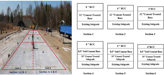
Figure 1
Constructed RCC test sections at PRF
A thickness design procedure specifically for the design of thin RCC-surfaced pavement structure was proposed. The procedure, modifi ed based on the PCA’s design methodology for un-doweled jointed plain concrete pavements, would consider both the fatigue and erosion analyses for a thin RCC-surfaced pavement thickness design.
Results from a construction cost analysis demonstrated that, by directly comparing two pavement design alternatives with a similar pavement design life, the initial construction cost savings for a 5-in. RCC slab over a 7-in. HMA surfacing would be approximately $113,087 per lane mile and $2,261,740 for a typical 2-lane, 10-mile long roadway project.
Conclusions
In the end, four thinner RCC pavement sections (Figure2) were severely damaged due to fatigue cracking. Through the laboratory and field investigations on thin RCC pavement performance, the following observations and conclusions were made:
- A thin RCC over soil cement pavement structure has a superior load carrying capability. The 6-in. RCC sections carried an estimated 87.4 million and 19.4 million ESALs to failure for the strong and weak base, respectively. The 4-in. RCC section on the strong base performed well with an estimated 19.2 million ESALs to failure;
- Load-induced fatigue cracks developed on thin RCC slabs were at first observed linearly along the traffic loading direction (or longitudinal direction) on pavement surfaces under tire prints. With continuous load repetitions and crack/joint pumping actions, voids could be formed underneath a thin RCC slab, which generated more deflections and propagated linear cracks into a fatigue cracking failure.
- Post-mortem trench results found that the fatigue cracks were initiated either from the bottom or top of a thin RCC slab as well as on a saw-cut joint. Numerical simulation results revealed that the critical stresses in the beginning of loading are located at the bottom of a thin RCC slab along sawcut joints, which produces a transverse, bottom-up fatigue crack through the joint. In addition, weak subgrade areas would be the most prone locations for pavement cracking.
- Based on the forensic and critical flexural stress analysis results, a load-induced cracking failure mechanism of thin RCC-surface pavement was proposed. Basically, a thin RCC slab under traffic and environmental loading would be fatigue-failed due to a combination of both propagations of longitudinal and transverse cracks with a help of pumping effect. After the substantial propagation of the longitudinal cracking along the wheel path, the pavement may be viewed as separate slabs and the wheel loading can be considered as an edge loading.
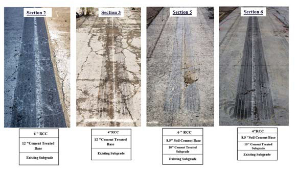
Figure 2
Four failed RCC sections
Recommendations
It is recommended that the Pavement Design Section begin implementing a new pavement design alternative using a thin RCC-surfaced pavement structure for DOTD’s low-volume roadways where heavy (and overloaded) trucks are often encountered. The recommended pavement structure consists of a thin RCC slab (usually 4~6 in.) built over a soil cement or cement treated base layer. The thickness design procedure provided in this study may be used in determination of the design RCC thickness. The RCC job mix formula (JMF) should have similar material compositions and gradation as those considered in this study, except that more fine aggregates and natural sands should be used in order to achieve the design roadway density and a ridable pavement surface (e.g., IRI = 100~120 in/mile). If the RCC pavement structure is to be used for high-volume roadways, surface diamond grinding or a thin asphalt overlay is recommended.